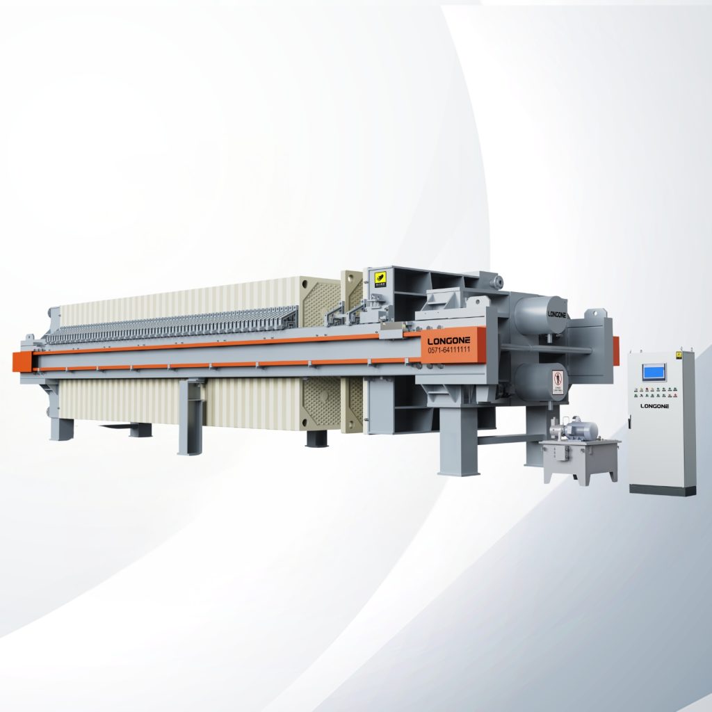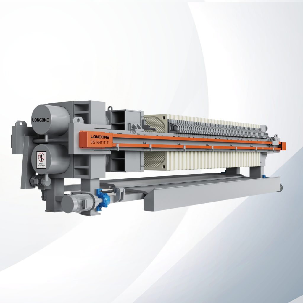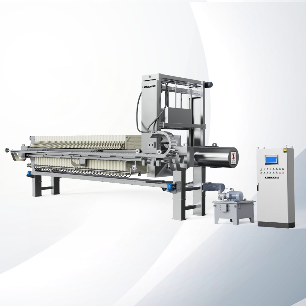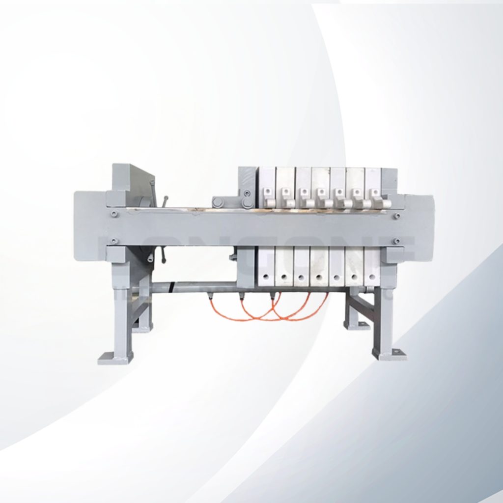
A filter press diagram is the single most useful document you can study before specifying, quoting, or troubleshooting a filter press — yet most diagrams circulating online strip away the details that actually matter to procurement teams and plant engineers. When feed port position, cloth fit, and closing pressure are simplified into a cartoon, buying decisions get harder and on-site problems take longer to diagnose.
A filter press diagram illustrates how a filter press separates solids from liquids by showing two layers: the mechanical frame (head plate, tail plate, side beams, hydraulic cylinder) and the filtration path (feed pump, feed channel, filter chambers, filter cloth, filtrate outlets, and cake discharge zone). Reading both layers together lets buyers verify supplier quotations, compare recessed-chamber and membrane designs, and pinpoint the root cause of uneven cake or leaking plates.
Below, I walk through each section of a typical filter press diagram in the order that matters most: components first, then the slurry-to-cake flow path, then the internal chamber detail that causes most performance issues. I also compare recessed-chamber and membrane layouts side by side, explain the sidebar beam frame design we use at LONGONE, and show you how to turn a diagram into a specification checklist and a troubleshooting guide.
Filter Press Diagram: The Main Components at a Glance
When you first open a filter press diagram, the sheer number of labeled parts can feel overwhelming — especially if you are comparing two or three supplier proposals at the same time. The instinct is to focus on frame size and hydraulic tonnage. But skipping the filtration-layer components is where most specification mismatches begin.
A standard filter press diagram labels between 12 and 20 parts. They fall into two groups: the mechanical frame (the structure that holds and compresses the plates) and the filtration assembly (the parts that actually contact slurry and produce cake). Understanding every labeled part — and the one common issue associated with it — saves hours during technical evaluation.
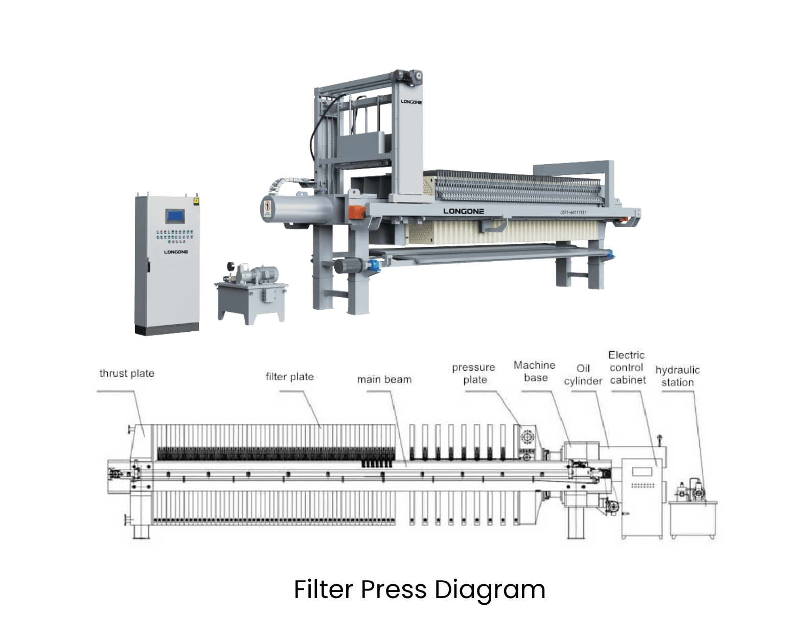
Component Reference Table
Below is a consolidated reference for the parts most frequently labeled on a filter press diagram. I have grouped them by layer and noted the issue we see most often in the field.
| Part Name | Layer | Function | Most Common Issue |
|---|---|---|---|
| Head plate (fixed end) | Mechanical | Anchors the plate pack; houses the feed inlet | Cracking at feed port weld due to hydraulic shock |
| Tail plate (movable end) | Mechanical | Travels along side beams to open/close the press | Misalignment after prolonged use |
| Side beams | Mechanical | Rails that support and guide the filter plates | Deflection under uneven plate loading |
| Hydraulic cylinder | Mechanical | Generates closing force to seal the plate pack | Insufficient pressure → plate leaks |
| Filter plates | Filtration | Form chambers when pressed together; drainage surface | Cracked corners, worn gasket surfaces |
| Filter cloth | Filtration | Retains solids while passing filtrate | Blinding, improper fit, cloth migration |
| Feed port / channel | Filtration | Distributes slurry into every chamber simultaneously | Blockage from oversize particles |
| Filtrate outlets | Filtration | Collect clear liquid from each plate and route it out | Clogged drain eyes |
| Drip tray / collection pan | Mechanical | Catches spillage during cake discharge | Overflow if not sized to cycle volume |
| Plate shifter (optional) | Mechanical | Automates plate-by-plate opening for cake discharge | Misaligned dogs, chain wear |
When reviewing a supplier’s diagram, check that every part in the table above is either labeled or explicitly noted as excluded. Omissions — especially around the feed channel layout and filtrate discharge routing — are red flags worth raising in a technical clarification round.
How to Read a Filter Press Flow Diagram: Feed, Filtrate, and Cake Paths
Engineers new to filter press procurement sometimes treat the flow diagram as decoration. Then, during commissioning, they discover the feed pump capacity does not match the chamber volume, or the filtrate piping was designed for open discharge when their process requires closed discharge. Reading the flow path before signing a purchase order prevents these surprises.
A filter press flow diagram traces three paths: (1) the feed path — slurry enters through the feed pump, passes through the head plate’s feed port, and fills every chamber via a central or corner channel; (2) the filtrate path — liquid passes through the filter cloth, flows along drainage grooves on the plate surface, and exits through filtrate outlets to a collection manifold; and (3) the cake path — retained solids build up inside each chamber until the cycle ends, the plates open, and cake drops by gravity into a hopper, conveyor, or truck below.
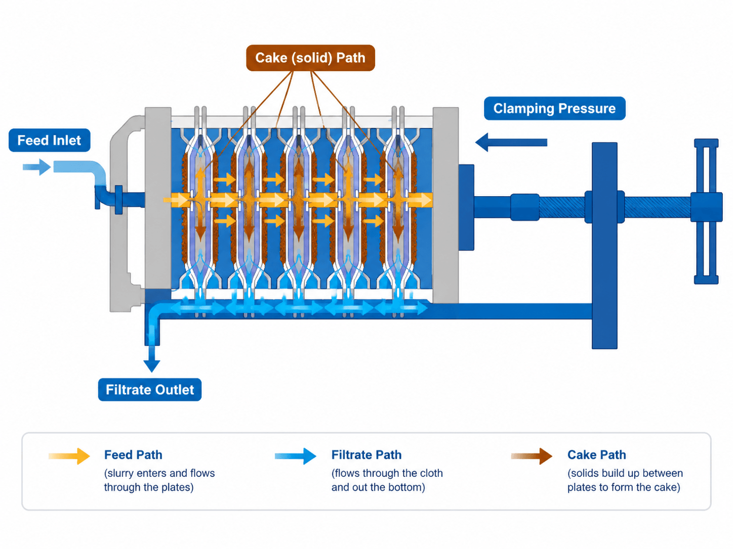
Reading the Feed Path
On most diagrams, a bold line runs from a feed pump symbol on the left into the head plate. Look for:
- Center feed vs. corner feed. A center feed port places the inlet at the geometric center of each plate. Corner feed places it at one of the four corners. Center feed distributes slurry more evenly in large-area plates (≥ 1,500 mm), while corner feed can be advantageous for high-solids slurries that benefit from slower, gravity-assisted filling.
- Feed pressure rating. The diagram or accompanying data sheet should specify maximum feed pressure — typically 0.6 to 1.6 MPa for recessed-chamber presses and higher for membrane presses during squeeze.
Reading the Filtrate Path
Filtrate exits are drawn as small arrows leaving each plate. Two configurations matter:
- Open discharge: Filtrate falls freely from individual plate spouts into a trough. Easy to monitor visually for cloth failure (cloudy filtrate from one spout = damaged cloth on that plate).
- Closed discharge: Filtrate is piped to a manifold under pressure or vacuum. Required when the filtrate is hazardous or when the downstream process needs pressurized delivery.
Reading the Cake Path
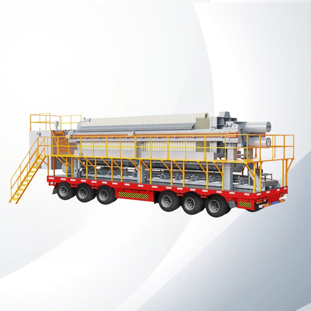
The diagram should show the gap below the plate pack. This gap determines how cake is collected — by gravity into a bin, onto a belt conveyor, or into a screw conveyor. If your plant layout constrains floor-to-plate clearance, flag this dimension early. I have seen projects delayed because the receiving conveyor did not fit under the press as drawn.
Inside the Chamber: Filter Plate and Filter Cloth Assembly
Most performance complaints we receive at LONGONE — uneven cake thickness, high residual moisture, plate-to-plate leaks — trace back to what happens inside the chamber, not to the frame or the hydraulic system. Yet many buyers spend 90% of their diagram review time on the external structure.
Inside each chamber, the filter cloth sits against the recessed face of a filter plate. Slurry enters through the feed eye, fills the chamber, and presses solids against the cloth while liquid drains through the plate’s surface grooves and exits via corner or center drainage ports. The gasket surface around the plate rim is the seal. If the closing force is insufficient or the gasket surface is worn, slurry bypasses the cloth entirely and sprays out as a leak.
Key Details to Check on an Internal Chamber Diagram
- Plate surface pattern. Pips (raised dots), grooves, or a combination. The pattern affects drainage rate and cake release. Ask the supplier which pattern they use and why.
- Cloth attachment method. Grommet, Velcro, or clip-in. Poor cloth retention causes migration — the cloth shifts during filling, creating thin spots in the cake and possible blowthrough.
- Chamber depth. Typically 25 mm to 50 mm per plate face (so 50 mm to 100 mm total chamber depth for a pair of recessed plates). Deeper chambers mean longer cycle times but thicker cake per cycle.
- Feed eye diameter. Undersized feed eyes restrict flow and cause uneven filling across the plate pack. Oversized feed eyes reduce gasket sealing area.
Takeaway: When a supplier sends you a filter press diagram, request a cross-section view of the chamber — not just the external elevation. This is where filtration quality is won or lost.
Recessed Chamber vs Membrane Filter Press Diagram: What Changes?
Choosing between a recessed-chamber press and a membrane filter press is one of the first specification decisions buyers face. The diagram differences between the two are surprisingly compact, but the operational implications are significant.
In a recessed-chamber diagram, every plate is identical — a rigid polypropylene or cast-iron plate with a recessed face on each side. In a membrane diagram, every second plate (or every plate) has a flexible membrane welded or heat-sealed onto one or both faces. After the filtration cycle, a secondary medium — compressed air or water — inflates the membrane to squeeze the cake, reducing moisture content further.

Comparison Table: Recessed Chamber vs Membrane Plate Diagram Differences
| Feature | Recessed Chamber Press | Membrane Filter Press |
|---|---|---|
| Plate construction on diagram | Single rigid body per plate | Rigid core + flexible membrane layer |
| Feed path | Feed pump → chambers → filtrate outlet | Same initial path, plus secondary squeeze inlet |
| Additional piping on diagram | None | Squeeze medium supply line (air or water) |
| Chamber depth | Fixed (set by recess depth) | Variable (membrane inflates to reduce effective depth) |
| Cake moisture | Higher (typically 25–40% depending on material) | Lower (can reduce moisture by 5–15 percentage points) |
| Cycle time | Filtration only | Filtration + squeeze phase |
| Typical applications | Mining tailings, wastewater sludge | Chemical slurries, high-value solids recovery, strict disposal limits |
| Diagram complexity | Simpler — fewer lines | More complex — squeeze circuit, pressure controls |
When reviewing a membrane press diagram, confirm that the squeeze medium circuit includes a pressure regulator and a safety relief valve. Over-pressurizing the membrane damages the diaphragm and can crack the core plate — an expensive repair.
Sidebar Beam Frame and Hydraulic Closing System Explained
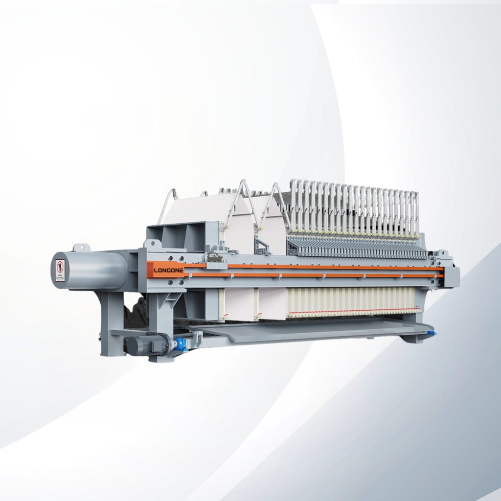
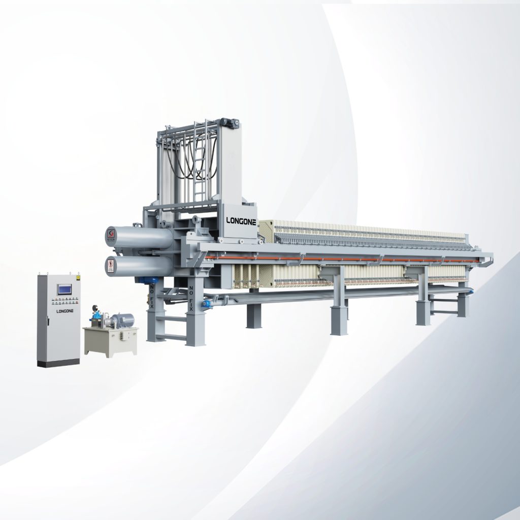
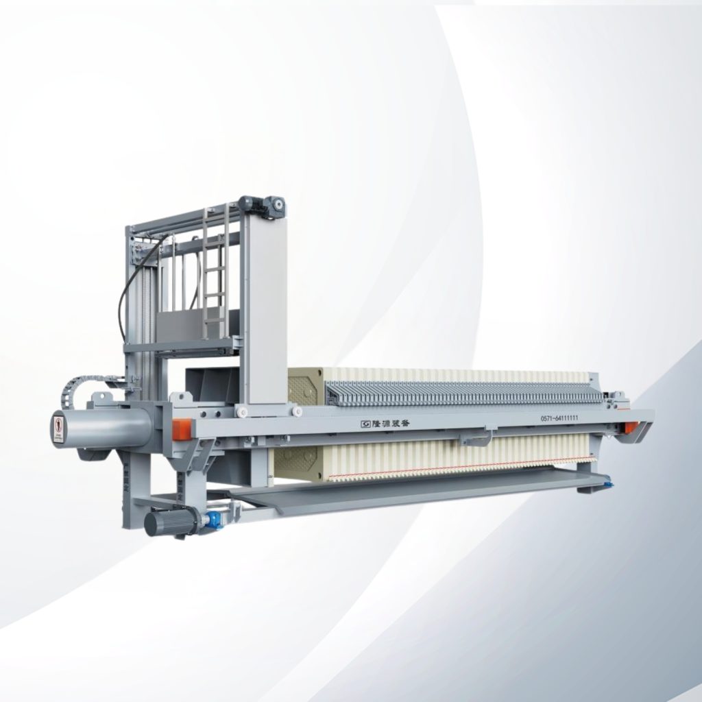
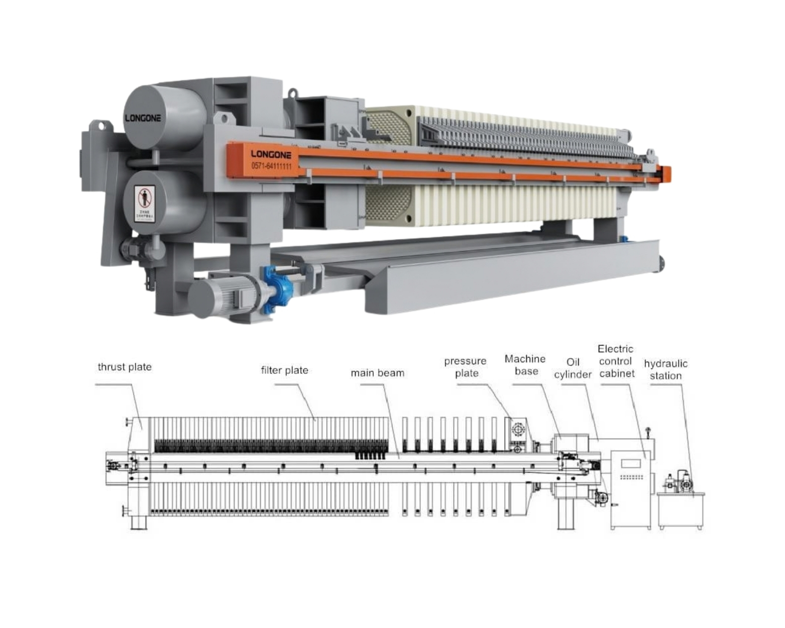
The frame design determines how plates are supported, how the press opens for cake discharge, and how much maintenance access you get. At LONGONE, we build sidebar beam filter presses — a design where two parallel beams (or four, on larger units) run along the sides of the plate pack and support the plates from below by their handles.
Why does this matter on a diagram? A sidebar beam layout places the structural members outside and below the plate pack. This means the top and sides of the press are open for inspection, cloth changes, and overhead crane access. On a diagram, you will see the side beams drawn as horizontal rails connecting the head plate to a thrust plate or support structure, with the hydraulic cylinder mounted at one end (usually the tail plate end).
Hydraulic Closing System
The hydraulic cylinder on the diagram is the component that generates the force to compress all filter plates together and seal the chambers. Key specifications to extract from a diagram or data sheet:
- Closing force (kN or tons). Must exceed the total chamber pressure × plate area to prevent leaks.
- Cylinder stroke (mm). Determines how far the plate pack can open for cake discharge and cloth maintenance.
- Hydraulic power pack location. Some diagrams show it mounted on the frame; others show a standalone unit connected by hoses.
Why Sidebar Beam Design Matters for Buyers
- Easier plate removal. Plates slide along the beams and can be lifted out individually for replacement.
- Better drainage. The open underside lets cake fall freely.
- Simpler structural inspection. Beam deflection and wear are visible without disassembly.
Note: LONGONE manufactures sidebar beam filter presses. We do not produce overhead beam designs. If your application requires an overhead beam configuration, we recommend consulting a qualified supplier who specializes in that frame type.
Using a Filter Press Diagram for Specification and Troubleshooting
A filter press diagram is not just an educational illustration — it is a decision tool. In procurement, it helps you ask better questions. On site, it helps you find problems faster.
During specification, a well-labeled diagram lets procurement teams verify that the quoted press matches their process requirements. During operation, maintenance engineers use the same diagram to isolate where in the flow path a failure is occurring — feed blockage, cloth blinding, gasket leak, or hydraulic pressure drop.
Specification Checklist (Derived from the Diagram)
- Feed configuration: Center feed or corner feed? Matches slurry characteristics?
- Plate type: Recessed chamber or membrane? Material (PP, cast iron, stainless)?
- Filtrate discharge: Open or closed? Number of outlets per plate?
- Closing system: Manual, semi-automatic, or fully automatic hydraulic?
- Frame type: Sidebar beam or overhead beam? Material and corrosion protection?
- Ancillary systems shown: Plate shifter, cloth washing, drip tray, conveyor?
Troubleshooting with a Diagram
| Symptom | Where to Look on Diagram | Likely Root Cause |
|---|---|---|
| Slurry leaking between plates | Gasket surface / closing cylinder | Insufficient closing pressure or worn gasket face |
| Uneven cake thickness | Feed channel / feed eye | Blocked feed port in one or more plates |
| High filtrate turbidity | Filter cloth / drainage ports | Cloth damage, wrong mesh size, or cloth migration |
| Slow filtration cycle | Feed pump / chamber depth | Undersized pump or excessive chamber depth for solids concentration |
| Hydraulic cylinder not reaching full stroke | Hydraulic power pack / cylinder | Low oil level, worn seals, or relief valve set too low |
By mapping every symptom back to a location on the diagram, your maintenance team can communicate precisely with the equipment supplier — reducing back-and-forth and accelerating resolution.
Frequently Asked Questions
What are the main parts of a filter press?
The main parts of a filter press include the head plate, tail plate, side beams (or overhead beam), hydraulic cylinder, filter plates, filter cloth, feed inlet, filtrate outlets, and drip tray. These divide into a mechanical frame layer and a filtration assembly layer, both visible on a standard filter press diagram.
How does slurry flow through a filter press?
Slurry is pumped through the feed inlet in the head plate, flows through a central or corner feed channel into every chamber simultaneously, presses against the filter cloth where solids are retained, and the resulting filtrate drains through plate surface grooves to the filtrate outlets. Solids build up as cake inside each chamber.
What is the difference between a recessed chamber and membrane filter press?
A recessed-chamber filter press uses rigid plates to form fixed-depth chambers. A membrane filter press adds a flexible membrane to one or both faces of certain plates, allowing a secondary squeeze phase that reduces cake moisture by 5–15 percentage points. The membrane press diagram shows additional piping for the squeeze medium.
Why does my filter press leak between plates?
Plate-to-plate leaks almost always originate at the gasket sealing surface. Common causes include insufficient hydraulic closing pressure, worn or damaged gasket faces on the plates, misaligned plates, or debris on the sealing rim. A filter press diagram helps isolate the leak location by mapping it to specific plates in the pack.
How do I use a filter press diagram to check a supplier’s quotation?
Compare every labeled component on the diagram against the quotation line items. Confirm feed configuration (center vs. corner), plate type (recessed vs. membrane), filtrate discharge method (open vs. closed), closing system type, and frame design. Any component shown on the diagram but missing from the quotation should be clarified before purchase.
Conclusion
A well-labeled filter press diagram is far more than a technical illustration — it is a specification checklist, a troubleshooting map, and a procurement verification tool. By reading both the mechanical frame layer and the filtration path layer, buyers can match equipment to process requirements, compare recessed-chamber and membrane designs with confidence, and diagnose on-site performance issues faster.
At LONGONE, we manufacture filter presses, filter plates, and filter cloths with over 20 years of production experience. If you are evaluating filter press options for your next project, our engineering team can provide detailed diagrams, cross-section views, and technical consultation tailored to your application. Reach out to start a conversation — we are happy to walk through the diagram together.